Last month in this space we showed that in areas where poor-quality seismic data are acquired across a high-velocity surface with surface-based geophones, good-quality reflection events are created at deep interfaces below this high-velocity surface layer.
Because good-quality reflections head upward toward the earth’s surface, why do we not capture these reflections with earth-surface receivers?
This month we will look at what appears to be the cause of this poor data quality – and consider one option for resolving the imaging dilemma.
The culprit that prevents the capture of good-quality reflection events often seems to be severe, unorganized ground-roll noise.
The earth model in Figure 1 will be used to illustrate the wave physics. There are two kinds of surface waves that travel horizontally away from a source station and spread across the earth-air interface:
- One surface wave is the Rayleigh mode, created by any surface-based source that produces a vertical displacement. Almost all onshore seismic sources (vertical vibrators, explosives in shotholes, weight droppers, etc.) create a vertical displacement and thus produce a Rayleigh wave.
The common term used for a Rayleigh wave is “ground roll.” The particle motion associated with a Rayleigh wave is a vertical, retrograde, elliptical motion as shown in Figure 1.
- The second surface wave that can propagate along the earth-air interface is a Love wave, which can be generated only by an SH shear source that creates pure horizontal displacement, and the wave propagates horizontally as a pure SH shear mode that produces no vertical displacement (Figure 1).
Of these two surface waves, the Rayleigh mode is the “bad” noise mode when the surface layer has a fast seismic propagation velocity. The Love wave is the “good” noise mode. You just have to love the Love wave when you operate in an area having high-velocity outcrops.
Why is the Rayleigh ground roll so troublesome across outcropping basalts and carbonates?
For most poor-data areas, the answer is that the exposed high-velocity layer usually has a rough surface and numerous large internal voids (see figure 1 of last month’s article), and these randomly positioned irregularities cause the ground roll to backscatter from many azimuth directions and at many different time delays to create a continuous overprinting of high-amplitude, unorganized noise on top of the deep reflection events that arrive at each surface receiver.
Because this noise is unorganized (i.e., it does not arrive from a fixed direction, and its components have variable time origins), it is difficult – and usually impossible – to remove from the data.
Upcoming reflections from deep targets do indeed arrive at the surface receivers as we suspected from last month’s discussion, but these reflections are overwhelmed by the reverberating, unending ground-roll noise.
How then can geology beneath a high-velocity outcrop be imaged?
The answer is a beautiful bit of wave physics explained in one or two textbooks and which is summarized by the following equation that defines the frequency components of a propagating Love wave:
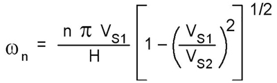
In this equation, ω is the frequency (Hz) of the Love wave, H is the thickness of the high-velocity surface layer, VS1 is the S-wave velocity in the surface-exposed layer and VS2 is the S-wave velocity in the interval beneath the surface layer.
When VS1 is greater than VS2, as it is when the surface layer is basalt or carbonate, the quantity inside the square-root bracket is negative, which results in an imaginary frequency. Because no Love wave can have an imaginary frequency, the physical consequence is that no Love wave propagates in this type of velocity layering, and there can be no surface noise mode.
If we therefore use SH shear technology to image beneath high-velocity outcrops, we have no surface-wave noise, and we should be able to capture SH reflections from deep targets.
One test of this principle – work done years ago by researchers at Arco – is shown above (Figure 2) to illustrate the physics.
The P-wave data are not too bad in the right half of the image space, where there is a slow-velocity earth surface, but the data are unusable on the left, where the profile moves onto the fast-velocity surface.
In contrast, SH data acquired along the profile produce a valuable image beneath both the low-velocity surface and the high-velocity surface and imply that there is a faulted trap below the fast-velocity surface that could be a good drilling target.
Excessive Rayleigh ground roll destroyed the P-wave reflections along the high-velocity surface. The absence of a Love surface mode on the high-velocity surface allowed SH reflections to be seen.
Think about using SH seismic technology if you have a bothersome high-velocity surface that hinders the use of P-wave data across a prospect area.